
Why Do Plastic Frame Molds Tend to Flash, and How Can It Be Solved from a Mold Design Perspective?
Why Do Plastic Frame Molds Tend to Flash, and How Can It Be Solved from a Mold Design Perspective?
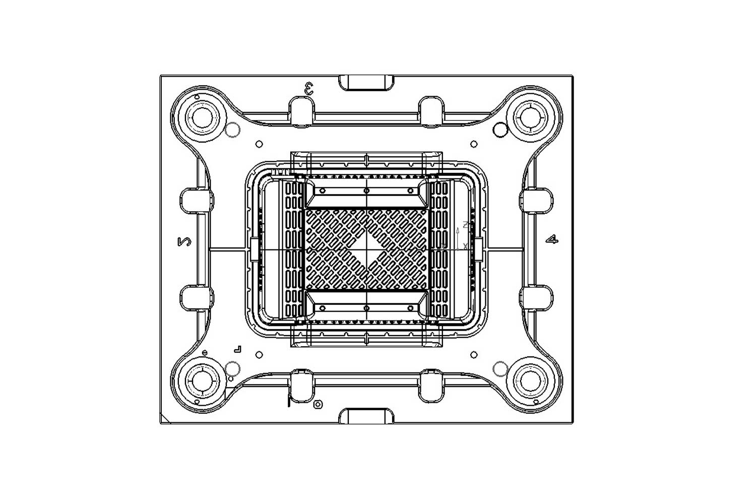
Anyone who has spent time on an injection molding floor is familiar with the term "flash." This is especially true when producing frame-type parts—whether it's an appliance face frame, a refrigerator door frame, or a side-mirror mounting frame. The scene of an operator standing next to the machine with a scraper, trimming burrs while the parts come out, is almost a daily routine.
Frame-type molded parts share a common set of characteristics: large overall dimensions, relatively thin walls, and often a closed or semi-closed ring structure. These geometric features make them a breeding ground for flash. Experienced technicians know that flash on frame molds is rarely caused by a single factor. Instead, it is the result of clamping force, mold rigidity, parting surface design, gate layout, and other factors conspiring under injection pressure.
To understand why flash favors plastic frames, we need to return to a basic physical fact: clamping force and injection pressure are locked in an eternal struggle.
The clamping force provided by an injection molding machine is limited, while the cavity pressure generated by the plastic melt during filling will try to push the moving and fixed halves apart. For frame-type parts, this problem is amplified by geometry. The center of a frame is usually empty, which means the injection pressure acts mainly on the annular projected area of the frame. This ring area may not be small, but its "supporting structure"—the closing surface on the mold parting plane that resists the separating force—lacks rigid support from the central region because the middle of the product is hollow.
What makes it worse is that the perimeter of a frame often has corners, ribs, or snap-fit features, and these locations tend to produce local pressure peaks. If the parting surface does not fit tightly enough, or if the mold lacks rigidity in these areas, the melt will squeeze out through tiny gaps just like water seeping through a weak spot in a dam, and once cooled, it becomes flash.
From a Mold Design Perspective, Where Do We Block the Path to Flash?
Once the cause is understood, the solutions become clear. The essence of flash is that "the melt has found a gap where it should not be." Therefore, the core task of mold design is to ensure that, throughout the entire injection cycle, there is no gap in critical areas through which the melt can penetrate. The following points should be addressed at the design stage.
First, clarify the "contact logic" of the parting surface.
In traditional design, the parting surfaces of the moving and fixed halves often fit together completely across the entire surface. For small products, this is fine. But for large frame molds, requiring the entire large area to achieve a perfectly tight fit is extremely difficult to machine and assemble, and very costly. A smarter approach is: only create a high-precision closing surface within a certain range immediately adjacent to the cavity perimeter, and make the rest of the area a relieved surface.
A relieved surface means leaving a gap of 1 mm to 3 mm between the moving and fixed halves, so they do not make direct contact. This way, when the mold closes, the area that truly needs precision fitting is greatly reduced. The workload for machining and grinding goes down, and the quality of the fit becomes easier to guarantee. The width of this "closing surface" matters: when the template width is less than 500 mm, use 20 to 40 mm; when it is greater than 500 mm, use 30 to 60 mm. Frame-type products usually fall into the latter category and need a sufficiently wide closing band to block the melt's path.
Second, use a "back-pressure" approach to counter local high pressure.
If the wall thickness near the parting surface of a frame-type product is uneven, the thick-wall areas will generate higher local pressure during the packing stage and push the parting surface open. There is a mold structure specifically designed to deal with this: on the inner side of the parting surface, near the cavity, design a tiny boss that mates with a reduced-thickness groove on the product to form a very thin "flow-stop lip."
The end face of this boss is 0.3 to 0.5 mm higher than the main parting surface, and its width is one-third to one-half of the main wall thickness. Its mechanism is: when the melt tries to escape from the parting surface, it must first pass through this extremely thin region, where the melt rapidly cools and forms a frozen layer, plugging itself off. It is like adding an inconspicuous low wall on the inner side of a dam—before the flood even reaches the real dam, it has already solidified.
Third, venting must be adequate, but vent grooves must not become "material discharge grooves."
Frame-type products often have multiple melt streams converging at the end of filling. If venting is poor, the compressed air creates an outward pushing force that opens the parting surface. Vent grooves are necessary, but their depth must be precisely controlled.
Here is an easily overlooked troubleshooting logic: if the flash thickness is less than the vent groove depth, then the vent groove is indeed an "accomplice" and needs to be made shallower. But if the flash thickness is greater than the vent groove depth, then the problem is not the vent groove itself—the parting surface is being pushed open by a greater force, and the vent groove is merely a "victim." Many mold technicians weld vent grooves shut as soon as they see flash, only to end up with wasted effort because they never found the root cause.
Fourth, the choice of gate position and number directly affects pressure distribution.
Gate design for frame-type products is a dilemma: too few gates means the flow length ratio is too large, requiring very high injection pressure to fill, and higher pressure makes flash more likely. Too many gates means more weld lines, which may affect appearance, and multiple gates mean multiple melt streams "fighting" within the narrow cross-section of the frame, making local pressure peaks more complex rather than less.
Research on large frame-type molded parts (such as mirror frames and air-conditioner face frames) shows that using mold flow analysis to determine gate positions and the number of injection points can help find a better balance between filling pressure and flash risk. For frame-type products, multi-point gates combined with a balanced runner design are often more effective than a single large gate at controlling cavity pressure distribution and reducing flash tendency.
Beyond Design: The "Hidden Variables" That Cannot Be Ignored
Getting the mold design right does not mean flash automatically disappears. There are several factors that, while not part of the design category itself, will still bring flash knocking if space for them is not reserved during design.
Selection of mold material.
The parting surface must withstand repeated clamping impact and melt extrusion. If the steel hardness is insufficient, the edges of the parting surface will quickly wear and collapse, and the gap will grow larger and larger. For products prone to flash, the parting surface area can use pre-hardened special steel with a hardness of around HRC30, significantly improving wear resistance.
Rigid support of the mold.
The center of a frame mold is empty. If the support plate or spacer blocks of the moving half lack sufficient rigidity, the injection pressure will bend the entire moving half, opening the parting surface in the central region. During design, sufficient margin must be reserved in mold base selection and support pillar arrangement.
Fit of slides and inserts.
Frame-type products often require side core-pulling to handle undercuts, and the sliding fit surfaces of slides and the fit clearances of inserts are also high-risk areas for flash. The control of fit clearances in these locations must be included in the tolerance chain calculation at the design stage, rather than being handled "by feel" during assembly.
Flash is one of the most "stubborn" injection molding defects because it is never caused by a single factor. For plastic frame molds, rigidity loss caused by large dimensions, uneven pressure distribution caused by the ring structure, and complex geometric features around the parting surface together create the conditions for flash to thrive. Solving it does not rely on a single "silver bullet," but on a systematic design approach covering parting surface strategy, local back-pressure structures, venting control, and rigid support. Only when these things are thought through at the drawing stage can the scraper on the shop floor be put down.
