
When Purchasing Molds, Which Parts of the Mold Drawings Provided by Suppliers Must Be Carefully Reviewed?
When Purchasing Molds, Which Parts of the Mold Drawings Provided by Suppliers Must Be Carefully Reviewed?
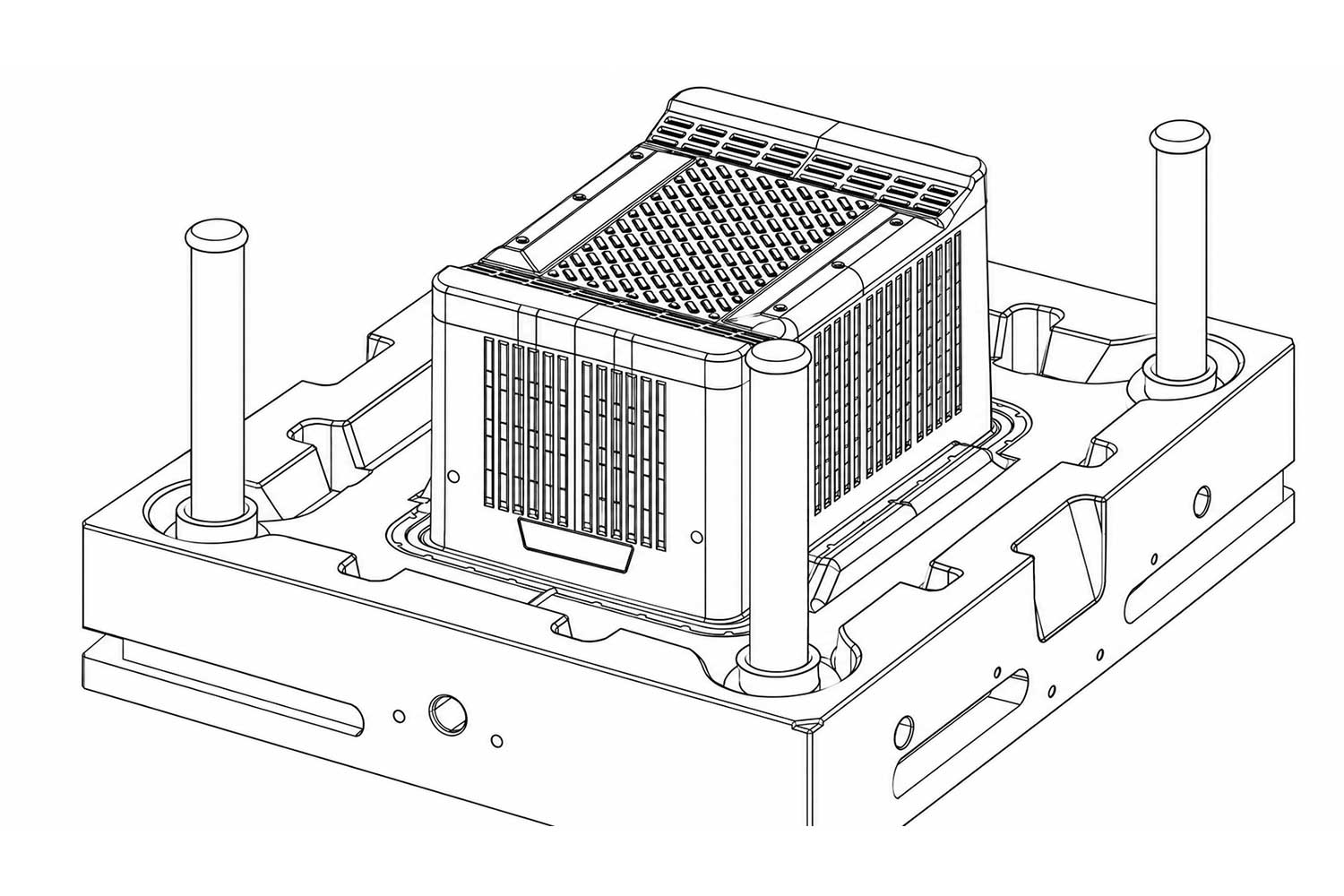
During the mold procurement process, many buyers focus their attention on quotations, delivery schedules, and contract terms, while the set of mold drawings sent by the supplier is often treated as an attachment to "go through the motions"—they open it, glance at whether the product shape is correct, and then file it away. By the time the mold arrives at the factory, problems appear during trial runs, and disputes arise over mold repairs, they discover that every place they failed to examine carefully on those drawings was a pit that had already been dug.
Mold drawings are not just an explanatory diagram of "what this thing looks like." For the buyer, they are the basis for acceptance, the evidence for accountability, and a window into whether the supplier truly understands the product requirements. What the supplier drew on the drawings, what they did not draw, what they annotated, and what they left vague directly determines whether this mold can ultimately produce qualified parts stably.
So when a set of mold drawings lands in your hands, which parts must the buyer carefully review?
First, Check the "Correspondence" Between the Product Drawing and the Mold Drawing
The drawings provided by the supplier usually contain two parts: the product drawing (or part drawing) and the mold structure drawing. The first thing to confirm is: do the dimensions of the cavity portion in the mold drawing correspond one-to-one with the dimensions in the product drawing?
This question sounds basic, but problems in actual practice are not uncommon. Some suppliers mark finished-product dimensions on the product drawing and cavity dimensions after shrinkage compensation on the mold drawing, but the two drawings do not clearly state which is which. If the buyer does not pay attention, they will measure the mold cavity against the finished product during acceptance and find that the numbers do not match.
What must be carefully reviewed is: how much shrinkage was applied, in which direction, and whether differences in shrinkage across different directions were distinguished. For frame-type, elongated, and rib-reinforced parts, the shrinkage rates in the longitudinal and transverse directions are often different. If the supplier only writes a single "1.005" and calls it done, while the product is clearly an anisotropic structure, that is a point that needs to be questioned.
Second, the Position and Form of the Parting Surface Determine Flash and Appearance
Where the parting surface is drawn directly relates to the appearance quality of the product and the subsequent trimming workload. The buyer does not need to be able to design the parting surface themselves, but they must understand where the supplier placed it and whether that placement is reasonable.
Focus on two things: whether the parting surface falls on a visible or functional surface of the product, and whether a sealing surface or back-pressure structure has been designed near the parting surface. If the parting surface runs right across a visible surface and the supplier has not done any sealing treatment, then after this mold goes into production, flash and parting lines will appear where the customer can see them, and the follow-up will require either additional trimming operations or mold modification.
Another easily overlooked detail is: whether the widths of the relieved areas and closing areas on the parting surface are annotated. A mature mold drawing should clearly mark which areas are precision-fit sealing surfaces and which areas are relieved surfaces with clearance. If the entire drawing only says "parting surface fits tightly" without specific zoning, it indicates that the supplier may not have seriously considered the issue of rigidity distribution in the design.
Third, the Position, Form, and Number of Gates
The gate is one of the parts of a mold drawing most worth the buyer's time, because it simultaneously affects three things: appearance, filling behavior, and subsequent processes.
What to look at: where the gate opens on the product, what form it takes (large gate, fine gate, pin-point gate, submarine gate, etc.), and how many there are. If the gate opens on a visible surface of the product and the product requires no trimming, then the supplier should be asked how they plan to handle the gate mark. If the product is a frame-type or thin-wall part, too few gates will cause an excessive flow length ratio, increase injection pressure, and raise the risk of flash; too many gates will increase weld lines, potentially affecting both appearance and strength.
For the buyer, there is no need to judge which type of gate is "best," but one thing must be confirmed: whether the gate scheme chosen by the supplier matches the product's appearance requirements, material characteristics, and the specifications of the injection molding machine. If the drawing shows only one gate position while the product clearly requires multi-point injection, that is a question that should be raised before the mold is cut.
Fourth, the Layout of the Ejection System
The ejection system on a drawing is usually a collection of symbols and position annotations for ejector pins, sleeve ejectors, and stripper plates. Buyers tend to think this is "the mold maker's own business," but in reality, the position and method of ejection directly affect whether the product can be demolded smoothly and whether there will be stress marks, deformation, or cracks after ejection.
What to look at: where the ejector pins are placed on the product, what their diameters are, and whether they land on thin walls, visible surfaces, or weak load-bearing areas. If the ejector pins push on a visible surface of the product while the product does not allow ejector pin marks, then the supplier needs to switch to another ejection method or move the pins to a non-visible surface. If the number of ejector pins is obviously too few, or they are concentrated in one area, the product may be pushed out of shape during demolding.
For frame-type products, special attention should be paid to: whether there is sufficient ejection support at the corners and the middle of the long sides of the frame. If ejection is insufficient in these locations, the frame edges will be bent or whitened during demolding.
Fifth, the Layout of Cooling Channels
Cooling channels often appear on drawings as a set of dashed lines or section lines. They look inconspicuous, but they determine the injection cycle and product deformation. What the buyer should look at: whether the distance from the channels to the cavity surface is uniform, and whether they reach the thick-wall areas and corner areas of the product.
If the drawing shows only a few straight-through pipes without conformal design tailored to the product shape, then the cooling efficiency of this mold is likely unsatisfactory, the molding cycle will be longer, and the product may warp due to uneven cooling. For frame-type parts, cooling at the long sides and corners is especially critical. If cooling is insufficient in these locations, shrinkage after demolding will be inconsistent, and the straightness and flatness of the frame will be difficult to guarantee.
The buyer does not need to design the cooling channels themselves, but they can ask one question: what is the estimated cooling time for this mold, and has the cooling channel design been verified by mold flow analysis? If the supplier cannot answer, or if the correspondence between the channels and the cavity cannot be seen on the drawing, that is a risk signal.
Sixth, the Fit Clearances of Slides, Lifters, and Inserts
If the product has undercuts, side holes, or internal snaps, the mold will have slides, lifters, or inserts. The fit clearances of these moving components are high-risk areas for flash.
What to look at: how much clearance is annotated on the mating surfaces of slides and lifters, and what the fit tolerance is between inserts and the mold core. If the clearance is too large, the melt will penetrate during injection and form flash; if the clearance is too small, the mold will seize or gall after thermal expansion. A serious mold drawing should annotate explicit fit tolerances at these locations, rather than vaguely writing "fit machining."
In addition, check whether the stroke of the slides and lifters is sufficient. If the annotated stroke is less than the actual depth of the undercut, the product will be scratched during demolding. The buyer can compare the undercut dimensions on the product drawing with the stroke annotations on the drawing to see whether there is an obvious insufficient margin.
Seventh, Mold Material and Heat Treatment Requirements
Mold drawings usually specify the materials and heat treatment hardness for the mold core, mold base, slides, and other main components in the title block or technical requirements. What the buyer should look at: whether these material specifications match the production volume requirements of the product.
If the expected production volume is several hundred thousand pieces, while the mold core material is only listed as ordinary P20 with no hardness requirement, then the service life of this mold may not last until the end of mass production. If the plastic used for the product is corrosive (such as PVC or materials containing flame retardants), and the mold material has not been corrosion-treated or stainless steel selected, the mold core surface will quickly rust or corrode.
The buyer does not need to be a materials expert for this part, but they need to make a basic comparison between the material annotations on the drawing and the product volume and plastic type. If there is an obvious mismatch, the supplier should be asked to explain the reason or adjust the plan before the mold is cut.
Eighth, the "Unspecified Tolerances" and "Technical Requirements" on the Drawing
This is the most easily overlooked area and the one that causes the most disputes afterward. The corner of a mold drawing usually has a "Technical Requirements" section containing unspecified fillets, unspecified tolerances, surface treatment requirements, assembly requirements, and so on. Buyers often only look at the graphic portion and do not read these texts carefully.
What must be carefully reviewed: what standard the unspecified tolerances follow, what the unspecified fillet is, what the fit precision requirement for the parting surface is, and whether a mold closing test is required after assembly. These texts may seem trivial, but they are the basis for acceptance. If the drawing states "unspecified tolerances per GB/T 1804-m" while the buyer requires a stricter standard during acceptance, the two parties will disagree. Conversely, if the drawing states nothing at all, there is no basis for acceptance, and the supplier can say "this clearance is within a reasonable range."
Ultimately, the Drawing Is the "Technical Contract" Between the Buyer and the Supplier
Mold drawings are not just machining instructions for the mold maker. They are also the technical agreement between the buyer and the supplier regarding "what this mold must look like to be considered qualified." The buyer does not need to be able to draw mold diagrams, but they need one ability: to see from the drawing which places have been taken seriously and which places have been glossed over.
A serious mold drawing has clear zoning on the parting surface, explanations of gate positions and forms, ejection layout logic, cooling channel routing rationale, tolerance annotations on mating surfaces, and executable standards in the technical requirements. A perfunctory mold drawing often has only the product outline and a few main dimensions, with everything else left to "we'll deal with it when the time comes."
And the parts left to "deal with when the time comes" are exactly the price the buyer will pay later.
